¶ When trying to flash the mainboard, the computer does not see the printer
The most common reasons are the following:
ch341ser_mac.zip
-
USB 3: several people have reported issues with USB 3 ports when trying to flash. There is no such issue with USB 2 ports.
-
Wrong baudrate . Your computer may have selected a wrong baudrate such as 9600. The default baudrate for this printer is 115200.
-
Missing USB driver . Most of the time, the operating system installs the right USB driver for the printer. But sometimes, the installation fails. The i3 Plus printer uses a cheap USB-to-Serial bridge WCH CH340G. The driver can be downloaded from the web site of the manufacturer (in Chinese). Since recently, this site seems to be difficult for some people to access. You can find a copy of the drivers here:
- For Windows: ch341ser.exe.zip
- For macOS: ch341ser_mac.zip
- for Linux: ch341ser_linux.zip
-
Bad SD card. Especially if you take an old one. Try with another card.
-
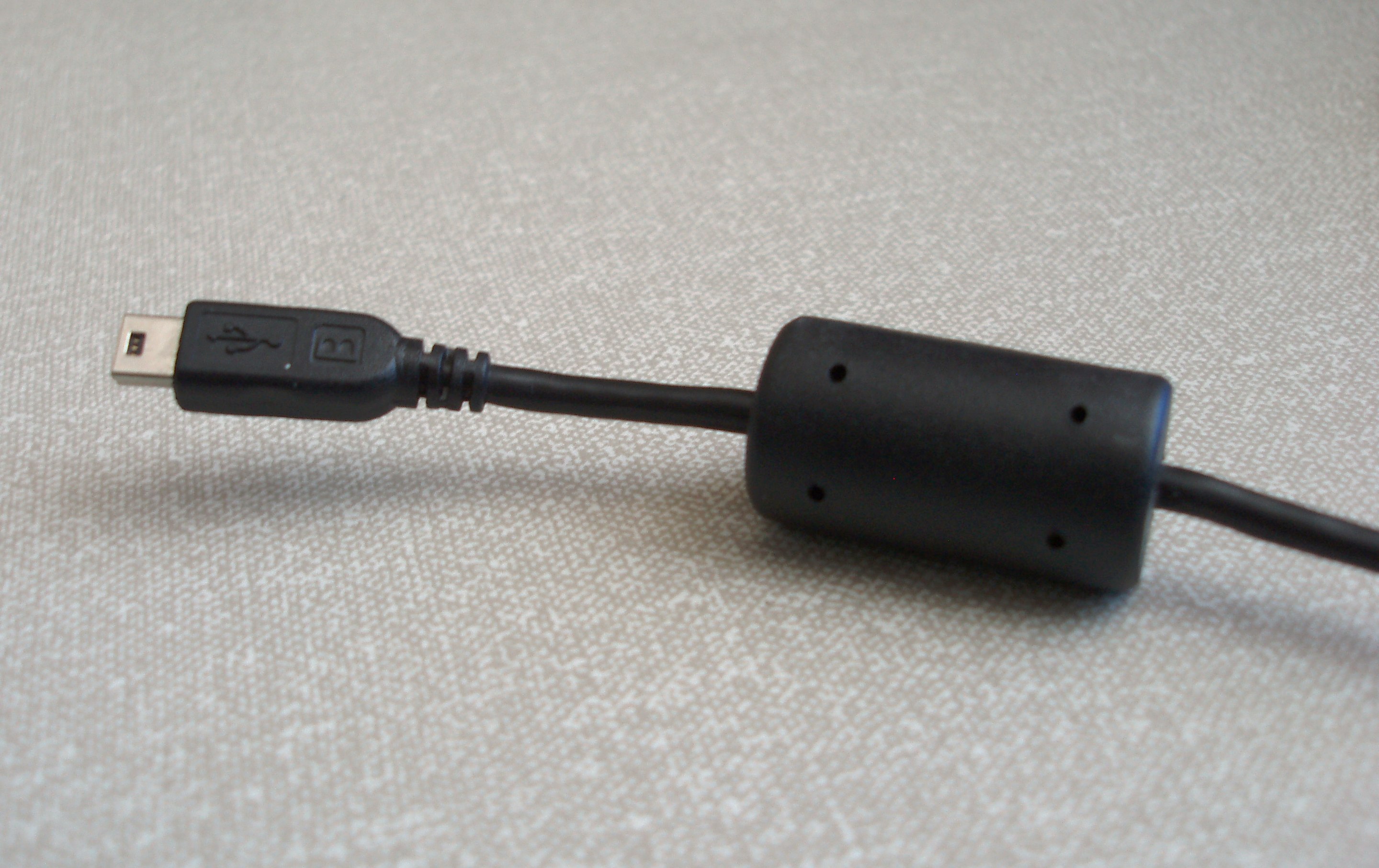
Bad USB cable . Try to use another, shorter, USB cable. It is also better to use a cable with a ferrite choke to reduce high frequencies:
¶ After flashing the firmware, I get an error in OctoPrint
You have either the stock firmware or a previous version of ADVi3++ and after flashing a new version of ADVi3++, you get the following error in OctoPrint:
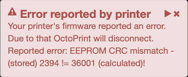
This is normal and expected. The firmware (stock or ADVi3++) stores its settings in a non-volatile memory called an "EEPROM" inside the microcontroller. When you flash a are firmware, these old values may be not compatible with the new firmware and can't be used. So the new firmware will inform you (and in this case OctoPrint) and display the following screen:
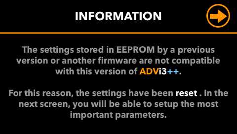
Simply press on the icon in the top-right corner. The settings will be reset by the new firmware to default values. You will have to either reenter the settings manually or use the different tuning screens (such as PID, Extruder Tuning, ...).
On the OctoPrint side, simply reconnect the printer.
¶ The left side is too close, the right side is too high (or the contrary)
This problems is, most of the time, related to the fact that the BLTouch sensor is not as the same position than the nozzle. Any asymmetry of the printer tends to be amplified.
¶ Square Z-frame
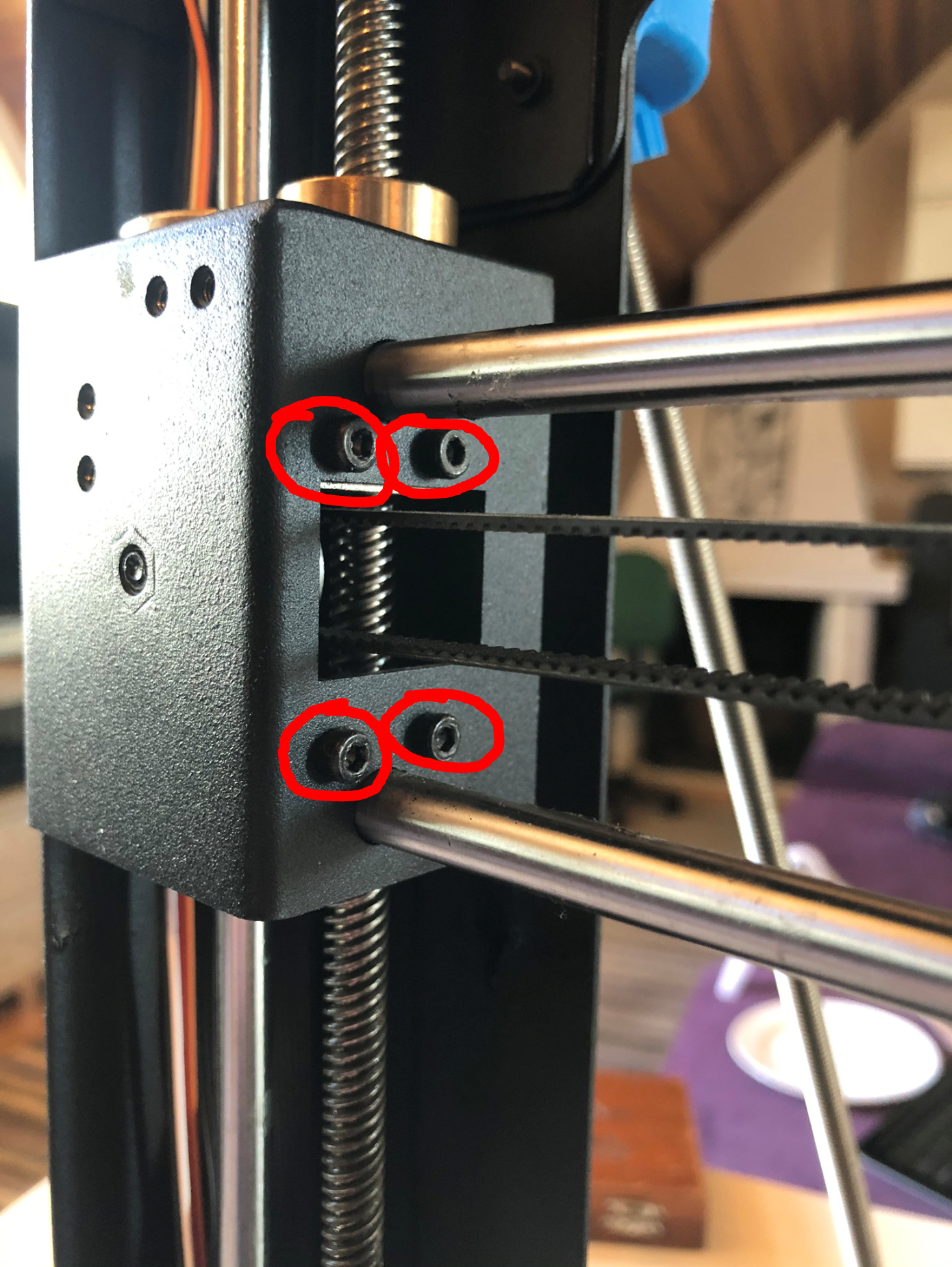
The first thing to do is to ensure that your top Z-frame is square:
Then ensure that the top Z-frame is perpendicular to the bottom XY-frame:
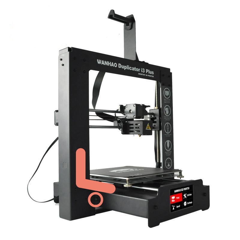
Use the four screws (see the circle) to adjust the position of the top Z-frame. It is important for the top Z-frame to be perpendicular to the bottom XY- frame , not the table or desk. It helps a lot if you are using Z braces (such as https://www.thingiverse.com/thing:921948 or a remix of it).
Then with a ruler, measure from the top left corner of the Z-frame, to the front left corner of the bed XY-frame with a ruler. Then repeat this measurement on the right side, the two measurements should be the same:
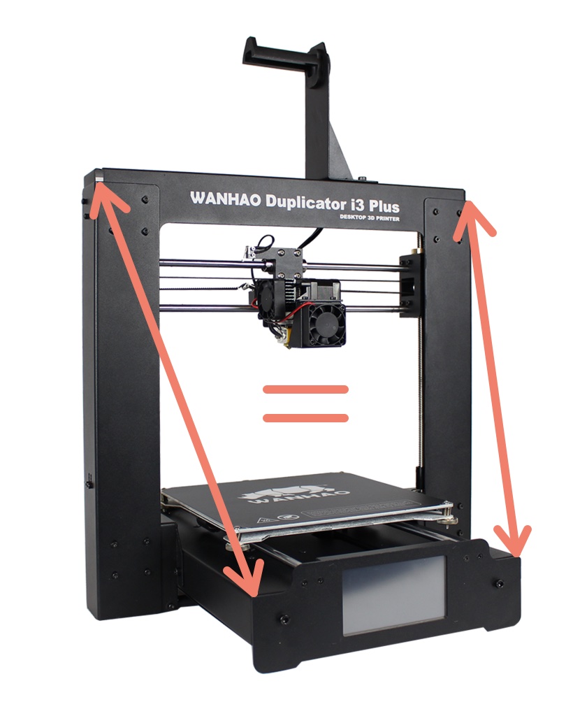
If the two measurement are not the same, it means there is a small twist in the Z-frame, that will result in a very small rotation of the X-carriage about the X-rails. This will result in the BL-Touch moving at a different rate from or towards the bed compared to that of the nozzle which is closer (thank you Ray Edgley for pointing this out).
¶ X axis
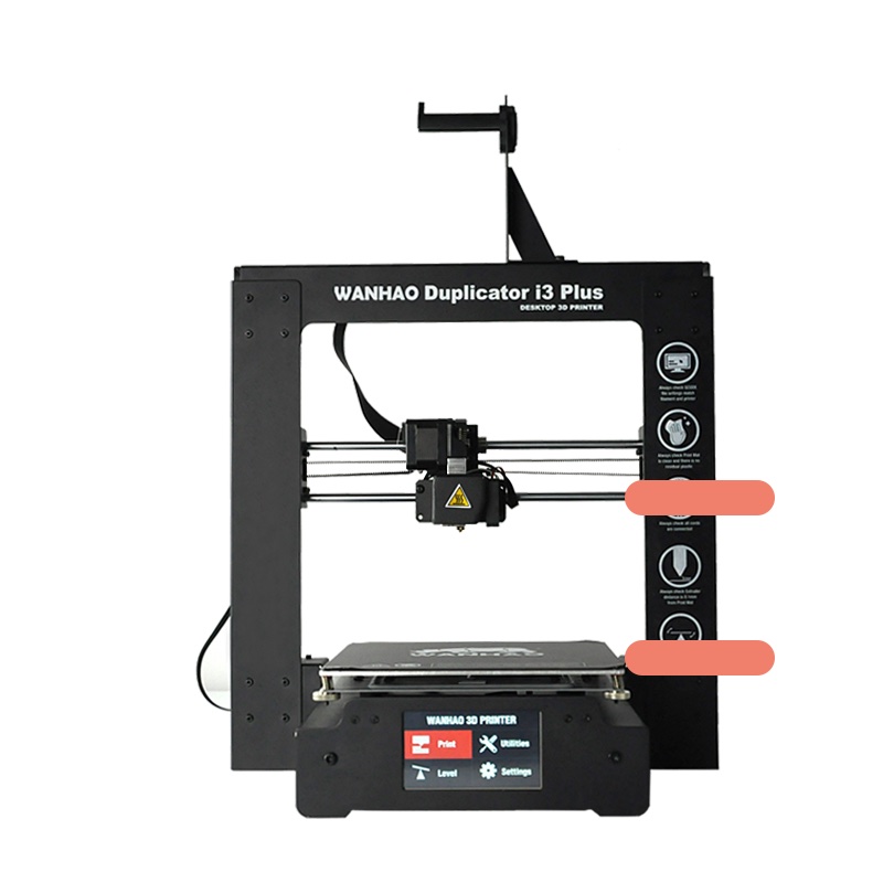
Then, and this step is very often overlooked, you have to ensure the X-axis is parallel to the bottom frame:
There are several possibilities to ensure that:
- Wanhao Duplicator i3 Z-Axis Alignment Posts (this is what I am using)
- Dual Z-axis alignment bars (I have not tested them, perhaps even better)
It is important to align with the frame (or rodes), not with the bed nor the table or desk. In this example, the x axis is not properly aligned:
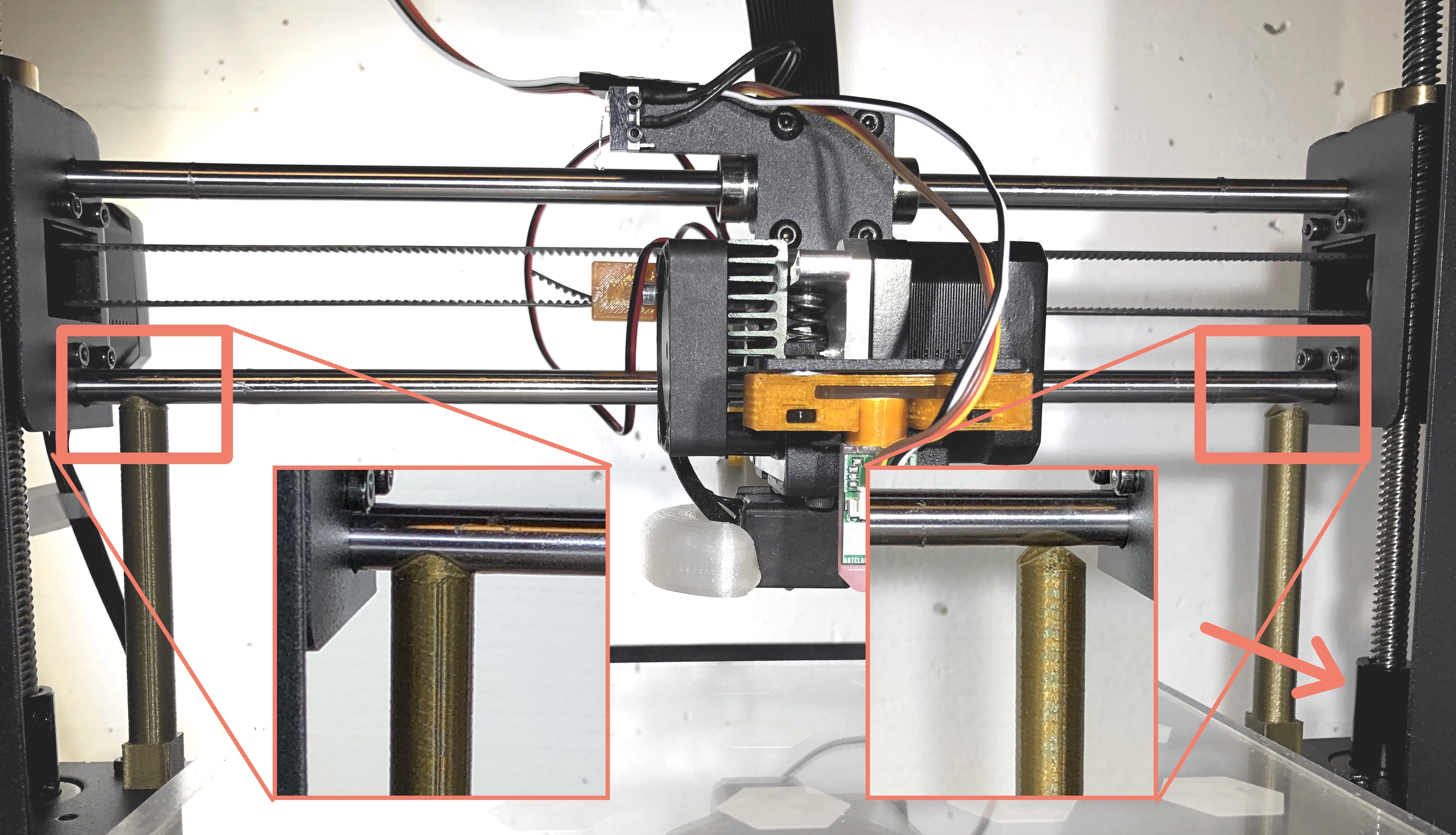
The left post touch the X-axis rode, but the right post does not. Move (gently) the z-axis rode on the right (see the arrow).
¶ Twist on the X axis
If, after ensuring your Z frame is square and the X axis is parallel to the bed, you still have a difference between the left and the right side, it is probably because your printer has a small twist on the X axis. The X axis has two rodes and any difference between the two will be amplified.
Here is a model of the X rodes and of the complete head with a BLTouch:
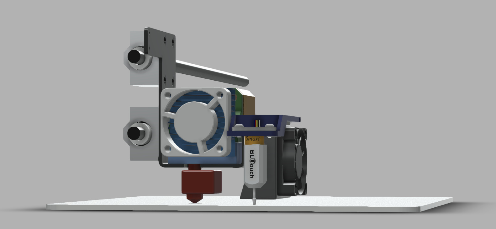
and a diagram explaining what happens:
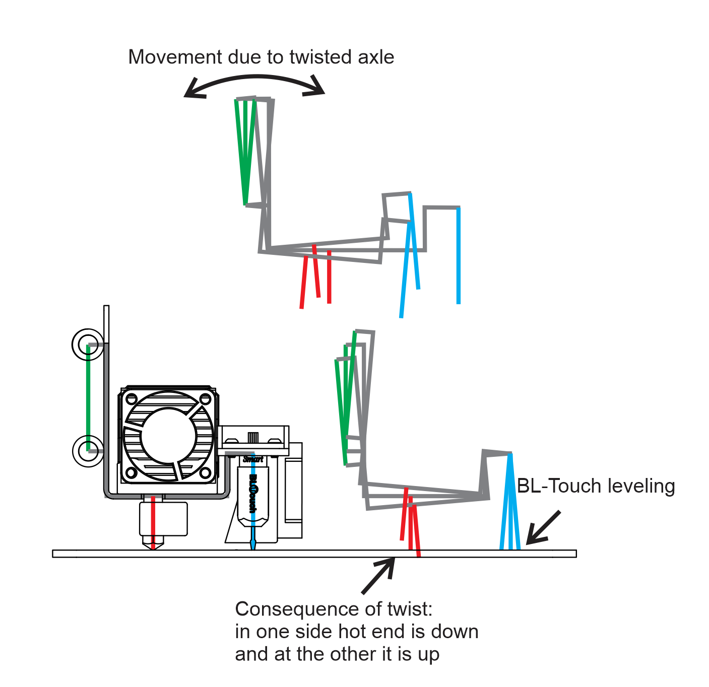
Note: Thank you to @MauroGil for creating this model and diagrams.
There are some hardware solutions, but not so easy in practice:
- Some people are pushing on one of the support of the x rodes
- Some people are releasing the external screws that support the X rods and retightened them in the correct position:
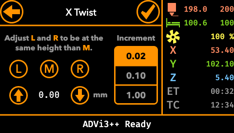
With version 5 of ADVi3++, there is now a software solution, as explained in the ADVi3++ User Manual.
¶ The LCD-Panel part does not flash properly
When you insert the microSD into the slot of the LCD panel, it should turn blue (after approximately 1 second) and then the pictures of ADVi3++ panels will be displayed one at a time. If it is not the case, there are several possible reasons:
-
The microSD card was not properly prepared. I highly recommend to use balenaEtcher. It is reliable, something that is often not the case with other software.
-
You choose the wrong file to flash the LCD. The file should have a name such as
ADVi3pp-LCD-5.0.0.img.zipwithimgin its name. -
Your microSD card is defective. This is a very common issue. Try with another, new, 8 GiB card. Avoid old microSD.
-
You use a microSD with a capacity higher than 8 GiB.
 The LCD panel is not able to read reliably high capacity cards. It is a limitation of the LCD panel. You can find plenty of them on AliExpress and eBay. They are however pretty rare now in physical stores.
 -
Some people have reported in the past issues with their anti-virus, but I do not have any details.
¶ The LCD panel behave strangely: When you press somewhere, it activates an element at a different place
You probably enter calibration mode by mistake or the LCD panel has forgotten its calibration parameters. There are different ways to solve this:
- Press the screen very rapidly 20 times.
- On a blank microSD card (8 GiB max), create a folder
DWIN_SET. In this folder, create aCONFIG.TXTfilewith the following content:
TP_CORRECT
- Use the image I already prepared with the right
CONFIG.TXT. Just write the image on a microSD card and insert the card into the LCD panel. The image is calledADVi3pp-CALIB-LCD-5.5.0.img.zipand is available in Binaries.
Notes
- I found method #1 difficult. Use method #3, it is the easiest.
- Previously I said here to create
CONFIG.TXTin the root of the microSD card. This is wrong. It has to be inside aDWIN_SETfolder. CONFIG.TXThas to containTP_CORRECTand nothing else.
¶ BLTouch unable to do automatic bed leveling: it stops when reaching the 1st leveling point
¶ Description of the problem
- You can z-home (after homing X and Y): the BLTouch goes to the center, deploys its pin, goes down, detects the bed and retracts.
- The problem appears (in particular), when you use automatic bed leveling:
- The BLTouch homes as before (X, Y and then Z)
- Then it tries to reach the first leveling point
- It stops entirely and just sits there. No movement, nothing
¶ Solution
- Your sensor settings are wrong and need to be adjusted
- Go to Settings / Leveling and adjust your X and Y offsets. To get the right values, you may have to measure them as described in the schema on the screen
- If you are using the recommended sensor supports, you just have to select the right one
¶ After reassembly, the LCD displays nothing
Be sure the flat cable between the LCD and the mainboard is properly inserted in its connectors. This cable and the connectors are very fragile.
The cable is a standard flat flexible (FFC) jumper cable, 1.0 mm pitch, 10 way. You can buy some from a local reseller. For example from RS-Online, manufactured by Wurth Elektronik .
¶ My LCD panel is corrupted, how to reset it?
This can happen if you use, for example, an old and bad microSD card. It may happen also if you use a microSD card with a capacity of more than 8 GiB. In those cases, you can reset the LCD panel (i.e. erase all its data) with the a special microSD image.
¶ Step 1 - Write the microSD image with balenaEtcher
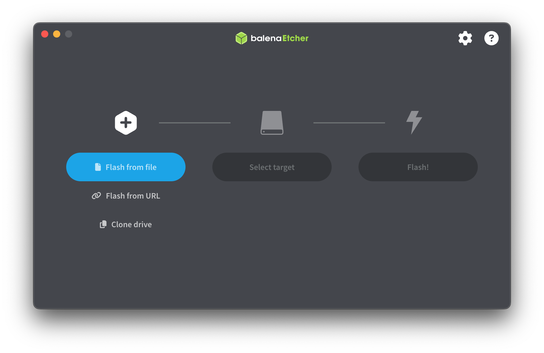
balenaEtcher is a great multi-platform tools used to flash SD cards and USB devices.
- Download the file called like
ADVi3pp-RESET-LCD-5.x.x.img.zip(LCD Reset microSD image) from Binaries - Download balenaEtcher from its website: https://www.balena.io/etcher/.
- Install it as you would install any application for your operating system.
- Be sure your 8GiB SD card is inserted in a slot of your computer.
- Start balenaEtcher.
- Click Select image and select the microSD card Reset image (such as ADVi3pp-RESET-LCD-5.5.0.img.zip)
- If your SD card is not automatically selected, click on Select drive and choose your SD card. Be sure to select the right device.
- Once you are ready, click on Flash!
¶ Step 2 - Install the microSD in its slot
- Disconnect the printer from power.
- Remove the two screws located on the front and loosen the two M3 grub screws on top of the linear rod holders.
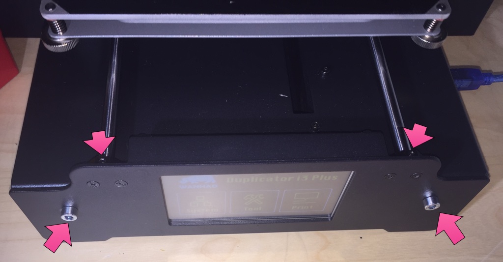
- Remove the front panel carefully (don’t break the flat cable).
- If you are lucky, you can insert the microSD card on the left of the panel (this is the case on the Monoprice clone).
- Otherwise, remove the four M3 screws and remove the cover
- Insert the microSD card in the slot.
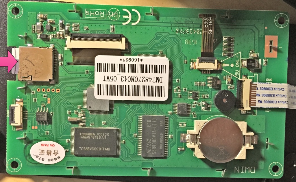
Note : Your LCD panel board may look slightly different as Wanhao uses different models depending on the phase of the moon.
- Turn on the printer; either by connecting it to power or by connecting the USB slot to the computer.
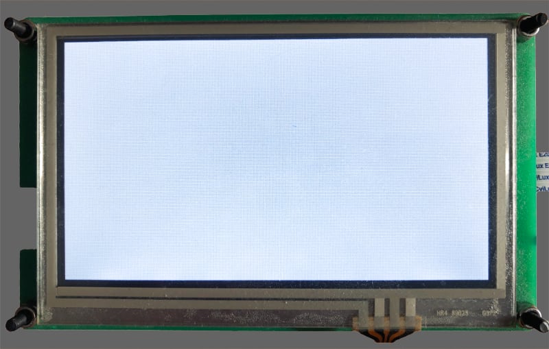
- The LCD panel will turn blue for a while:
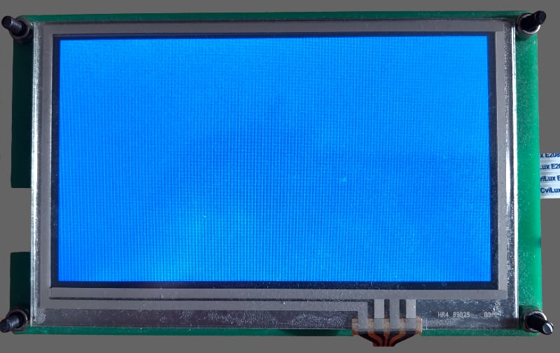
- After about 2 or 3 minutes, the LCD panel will turn gray:
- Turn off the printer and remove the microSD card.
The LCD panel is now reset. You can now proceed and install the LCD part of ADVi3++ as described in ADVi3++ User Manual - How to flash.